

Views: 0 Author: Site Editor Publish Time: 2026-08-26 Origin: Site


Procuring a Continuous Catenary Vulcanization system is a high-stakes capital expenditure that dictates your production ceiling, product quality, and operational overhead for decades. Scaling production to meet the demand for higher voltage classes requires overcoming complex physical challenges on the factory floor. You must manage heavy insulation weight, maintain strict concentricity, and ensure complete XLPE cross-linking without sacrificing line speed. Navigating the procurement process requires moving beyond basic spec sheets. You need to evaluate extrusion precision, curing tube thermodynamics, and closed-loop control systems. This guide provides a technical framework for evaluating and shortlisting a CCV line based on production targets, voltage requirements, and facility constraints.
Match Geometry to Voltage: The required catenary curve, tower height, and curing tube length must be mathematically aligned with the maximum intended voltage class and conductor cross-section.
Extrusion Precision is Non-Negotiable: A true Triple-Layer CCV Line for XLPE Cables is mandatory for medium and high-voltage applications to ensure void-free insulation and optimal electrical stress distribution.
Automation Drives Yield: Modern CCV lines rely on integrated X-ray measurement and closed-loop controls to minimize scrap, correct sag, and maintain concentricity in real-time.
Long-Term Costs Extend Beyond CAPEX: Long-term profitability hinges on operational efficiency, specifically nitrogen recovery rates, energy consumption in the heating zones, and OEM maintenance support.
Evaluating your production strategy is the first step in specifying equipment requirements. Determine if the line will run continuously on a single high-demand cable type or require frequent changeovers for varying cross-sections. High-mix environments demand rapid tooling adjustments and streamlined cleaning protocols. You must evaluate purge times, crosshead cleaning requirements, and tooling changeover speeds. Extended downtime between product runs severely impacts overall equipment effectiveness.
Material versatility also plays a major role in equipment selection. Determine if the line must handle only standard XLPE or if it needs to process cured rubber, EPR, or other cross-linked polymers for specialty applications like oil field cables, mining operations, or marine deployments. Equipment designed for multiple compounds requires highly adaptable thermal profiles and specialized screw designs. When processing EPR, for example, the extruder screw geometry must prevent excessive shear heating, which differs significantly from standard XLPE processing requirements.
To optimize changeovers in a high-mix facility, operators typically follow a strict sequence:
Ramp down extruder RPM and line speed simultaneously to clear the current compound.
Introduce the purge compound to push out residual XLPE before it cross-links in the barrel.
Extract the tooling (die and guider tip) while the crosshead remains at operating temperature.
Clean the flow channels using specialized brass tools to prevent scoring the polished steel surfaces.
Install the new tooling, verify alignment, and initiate the heat-soak process for the next run.
Cable manufacturing is heavily regulated. Your equipment must consistently meet stringent international specifications. Establish the specific international standards the end-product must meet, such as IEC 60502 for medium voltage, IEC 60840 for high voltage, or specific IEEE and AEIC requirements. These standards dictate acceptable tolerances for wall thickness, ovality, and partial discharge limits.
Achieving these tolerances requires exceptional mechanical stability from the extrusion crosshead and precise thermal management within the curing tube. Any deviation in concentricity or the introduction of micro-voids during the cross-linking phase will result in test failures and scrapped material. We frequently see operators struggle with partial discharge failures simply because the cooling gradient in the water zone was too aggressive, inducing mechanical stress in the insulation.
Standard | Voltage Class | Key Focus Areas for Extrusion | Typical Tolerance Requirements |
|---|---|---|---|
IEC 60502-2 | 6 kV to 30 kV | Basic concentricity, void-free insulation | Standard wall thickness minimums |
IEC 60840 | 30 kV to 150 kV | Strict sag control, smooth semicon interfaces | Tight eccentricity limits, zero micro-voids |
IEC 62067 | 150 kV to 500 kV | Absolute purity, extreme sag prevention | Ultra-tight tolerances, mandatory X-ray monitoring |
The physical footprint of a continuous vulcanization system dictates the scope of the project. Assess existing building height and length against the required catenary curve calculations. The catenary geometry must perfectly balance the gravitational pull on the molten insulation against the line tension. If the building is too short, the curing tube cannot be extended sufficiently to achieve desired line speeds.
Evaluate the feasibility and civil engineering costs of constructing a new extrusion tower or modifying existing infrastructure. Retrofitting an older facility to accommodate a modern, high-speed system frequently requires significant structural reinforcement. You must account for the foundation work needed to support the accumulator and payoff machinery. The extrusion tower itself requires isolated foundations to prevent ambient factory vibrations from transferring into the crosshead, which would immediately cause concentricity variations in the cable.
When specifying a CCV Line for LV/MV Power Cables, the primary focus remains on high line speeds, rapid material changeovers, and consistent output for high-volume markets. Medium voltage cables have relatively moderate insulation thicknesses, allowing for faster curing times and higher throughput. Technical requirements center around standard dry curing configurations, optimized cooling zones for medium insulation thicknesses, and robust tension controls for smaller conductors.
The primary evaluation metric for this category is the maximum line speed measured in meters per minute versus the guaranteed concentricity at the 35 kV insulation thickness. Manufacturers must balance the drive for maximum output with the physical limits of the cross-linking reaction to prevent under-cured products. Operators running these lines typically prioritize accumulator capacity, ensuring they can perform flying splices on the payoff without slowing the extruder down.
Stepping up to the 66 kV to 132 kV range introduces significant physical challenges. A Middle-High Voltage CCV Line must focus on managing heavier insulation weights and preventing insulation droop before cross-linking occurs. The thicker XLPE layer requires more time to reach the necessary cross-linking temperature throughout its entire volume.
Technical requirements include extended heating and cooling zones, precise conductor pre-heating to initiate curing from the inside out, and advanced sag control mechanisms. The evaluation metric shifts toward the system's ability to maintain uniform heat distribution and prevent deformation in thicker XLPE layers. Without precise thermal management, the outer layer may scorch while the inner layer remains insufficiently cross-linked. Conductor pre-heating becomes mandatory at this stage. By heating the copper or aluminum core to around 100°C before it enters the crosshead, you jumpstart the cross-linking process at the inner semiconductive boundary.
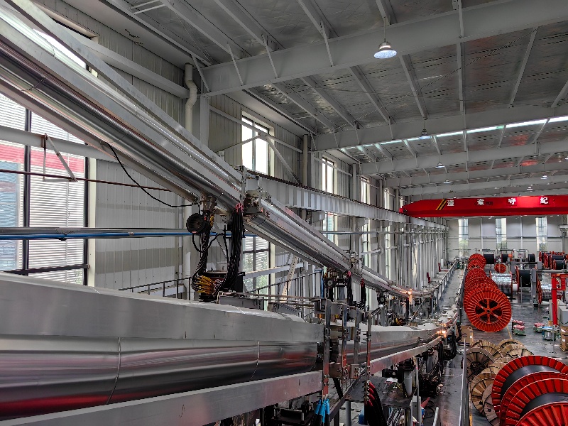
High Voltage (HV) and Extra High Voltage (EHV) applications demand extreme concentricity requirements, absolute purity of the insulation shield, and the ability to manage massive conductor weights. Technical requirements mandate specialized triple crossheads, ultra-clean material handling systems, and highly customized catenary geometries that often require significantly taller extrusion towers.
You must carefully evaluate the small conductor challenge. This involves assessing the system's capability to manage the critical ratio of considerable insulation weight supported by a relatively small conductor. This specific dynamic drastically increases the risk of insulation droop and eccentricity. The core evaluation metric becomes the long-term stability of the extrusion process and the precision of the closed-loop X-ray monitoring systems over extended production runs. At 220 kV, even a 0.1mm deviation in the outer semiconductive layer can create localized electrical stress points that lead to field failures.
The heart of any modern high-voltage cable operation is the extrusion crosshead. A Triple-Layer CCV Line for XLPE Cables is engineered to perform simultaneous extrusion. You must evaluate the capability of the crosshead to simultaneously apply the inner semiconductive layer, the XLPE insulation, and the outer semiconductive layer in a single pass. This co-extrusion process ensures flawless bonding between the layers, eliminating air gaps that cause partial discharge.
Assess the rheological design of the distributors to ensure balanced material flow. Proper flow dynamics prevent material stagnation and pre-curing, commonly known as scorch, within the crosshead. Review the integration of clean-room material feeding systems. Absolute purity is required to prevent contamination of the XLPE. Even microscopic impurities can lead to catastrophic dielectric failure in the field. The material handling system should utilize fully enclosed, pneumatically driven stainless steel piping, transferring the XLPE pellets directly from the clean room to the extruder hopper without any exposure to ambient factory air.
The thermodynamic efficiency of the curing tube directly impacts both product quality and operational overhead. Evaluate the design of the nitrogen-based dry curing zones. Look for multi-zone temperature controls that allow for precise profiling of the cross-linking process. The ability to fine-tune temperatures across different sections of the tube ensures that the XLPE cures uniformly without thermal degradation.
Assess the transition from the heating zone to the pressurized water cooling zone. Rapid or uneven cooling can induce micro-voids or severe mechanical stress within the cable structure. The cooling gradient must be carefully managed, often utilizing a warm water transition zone before the cable hits the chilled water section.
Review the systems responsible for handling and filtering cross-linking byproducts. During vulcanization, XLPE releases byproducts such as methane and acetophenone. Efficient extraction and filtration of these gases are necessary to maintain tube cleanliness, ensure consistent heat transfer, and uphold facility safety standards. If acetophenone builds up inside the tube, it can drip back onto the hot cable surface, causing severe surface defects and localized curing failures.
Consistent line speed is a prerequisite for uniform curing. Evaluate the capacity of raw cable core accumulators to maintain line speed and tension during reel changes. A properly sized accumulator prevents costly line stoppages and ensures the extrusion process remains uninterrupted while operators load new conductor reels. The accumulator carriage must move smoothly; any jerking motion will send tension spikes directly down the line.
Assess the precision of pay-off and take-up drives. These systems must apply exact tension to prevent conductor stretching or deformation before entering the crosshead and after exiting the cooling tube. Any fluctuation in tension will immediately alter the catenary sag, leading to eccentricity and out-of-spec wall thickness. We recommend utilizing dual-capstan systems with load cell feedback to isolate the curing tube tension from the heavy lifting required at the take-up reel.
Modern cable manufacturing relies heavily on advanced automation to maintain tight tolerances. The necessity of integrated, multi-axis X-ray measuring systems immediately following the cooling zone cannot be overstated. These systems continuously monitor wall thickness, eccentricity, and overall diameter.
Evaluate the software's ability to automatically adjust extruder RPM, line speed, and tube temperatures based on real-time X-ray data. This closed-loop feedback eliminates human error and minimizes scrap rates. Ensure seamless integration between extruder drives, capstans, and curing tube controls to maintain absolute tension stability across the entire line.
Assess the SCADA system's capacity to log production parameters for every meter of cable. Comprehensive data logging provides full traceability, which is essential for quality audits, client verification, and post-production failure analysis. If a cable fails a high-voltage test in the lab, the engineering team must be able to pull the exact extrusion temperatures, line speeds, and nitrogen pressures for that specific meter of cable.
Procurement decisions require balancing upfront capital expenditure against ongoing operational expenses. High-efficiency heating elements and heavily insulated curing tubes require a higher initial investment but drastically reduce daily energy consumption over the equipment's lifecycle. You must evaluate the efficiency of the nitrogen sealing and recovery systems. The curing process requires a highly pressurized nitrogen atmosphere to prevent oxidation and moisture ingress. High nitrogen leakage rates significantly inflate operational expenses.
Consider the trade-off between facility footprint and production output. A longer curing tube increases the maximum achievable line speed and overall output but requires a larger, more expensive facility footprint and a taller extrusion tower to maintain the correct catenary geometry. Shortening the tube saves on civil engineering costs but permanently caps your maximum production speed, forcing you to run slower to achieve the required cross-linking time.
Operators frequently face the temptation to push equipment beyond optimal parameters to meet production quotas. You must understand the physical limits of XLPE cross-linking. The chemical reaction requires a specific time-at-temperature to achieve the necessary gel content. Pushing line speeds beyond the thermodynamic capacity of the curing tube results in under-cured insulation, which inevitably leads to catastrophic cable failure under electrical load.
Balancing the equation requires sophisticated planning. Evaluate OEM simulation software that predicts maximum safe line speeds based on conductor size, insulation thickness, and specific XLPE compound characteristics. These predictive models allow engineers to optimize throughput without compromising the structural integrity of the insulation. The software calculates the exact point within the tube where the inner layer reaches the cross-linking threshold, ensuring the cable is fully cured before it hits the water cooling zone.
When manufacturing extra-high-voltage cables, engineers must evaluate alternative extrusion methods. For EHV cables, typically those rated 400kV and above, you must evaluate if a catenary geometry can adequately prevent eccentricity. In some cases, the extreme insulation thickness necessitates the vertical extrusion process of a VCV line, where gravity pulls the cable straight down, eliminating sag entirely.
Facility impact is a major consideration. VCV lines require massive vertical towers, often exceeding 100 meters in height. This makes catenary systems a much more viable and practical option for cables up to 220kV or 275kV, provided that advanced sag controls, precise thermal management, and rotating caterpillar systems are properly implemented.
System Type | Optimal Voltage Range | Primary Advantage | Facility Requirement |
|---|---|---|---|
Standard CCV | Up to 35 kV | High throughput, rapid changeovers | Standard industrial length, low tower |
Advanced CCV | 66 kV to 132 kV | Excellent balance of speed and concentricity | Extended length, medium tower height |
Heavy-Duty CCV | 220 kV to 275 kV | Handles heavy insulation with sag control | Significant length, tall extrusion tower |
VCV (Vertical) | 400 kV and above | Zero gravitational sag, perfect concentricity | Massive vertical tower (100m+) |
Deploying heavy industrial extrusion equipment requires meticulous project management. Mitigate delays by finalizing tower and foundation requirements with the OEM before finalizing the equipment purchase. Civil engineering dependencies often cause the most significant project bottlenecks. Pouring reinforced concrete foundations for the pay-off machinery and erecting the extrusion tower must be perfectly synchronized with the equipment delivery schedule.
Plan for a structured, phased commissioning process. Start with dummy cables and low-voltage runs to calibrate tension controls and thermal profiles before attempting high-voltage production runs. Rushing the commissioning phase frequently results in damaged tooling, severe crosshead scorch, and wasted raw materials. You need to verify the alignment of the entire catenary tube using laser measurement tools before introducing any heated polymer into the system.
The most advanced extrusion hardware will underperform if the operational staff lacks the necessary expertise. Transitioning from older, manually controlled CV lines to highly automated systems requires significant operator upskilling. The skills gap is a tangible risk to production yields.
Mandate comprehensive on-site training and shadowing from the OEM during the first months of production. Operators must understand how to interpret real-time X-ray data, manage closed-loop feedback alarms, and execute rapid tooling changeovers without introducing contamination into the clean-room environment. They need to know exactly how to respond when the SCADA system flags a sudden drop in nitrogen pressure or a spike in extruder barrel temperature.
Long-term equipment reliability depends heavily on maintenance protocols and the supply chain for replacement parts. Evaluate whether the machinery uses proprietary electronics or standard, globally available components. Systems built with standard PLCs and drives from major industrial suppliers ensure that replacement parts can be sourced locally, minimizing downtime.
Ensure the system includes secure remote access capabilities. Remote diagnostics allow OEM technicians to troubleshoot software anomalies or control issues rapidly from off-site locations. This prevents minor sensor faults from escalating into prolonged production halts. Your maintenance team should also maintain a strict schedule for replacing the high-temperature seals on the curing tube end-caps to prevent nitrogen leaks.
Audit your facility dimensions and structural load capacities before requesting equipment specifications to ensure the required catenary curve is physically viable.
Demand empirical simulation data from the OEM demonstrating guaranteed line speeds and concentricity tolerances for your specific conductor sizes and XLPE compounds.
Prioritize closed-loop X-ray measurement and automated thermal profiling to minimize operator error and reduce scrap rates during high-voltage production.
Establish a strict clean-room protocol for material handling to support the triple-layer extrusion process and prevent microscopic contamination.
Schedule comprehensive, on-site OEM training for your engineering and operational teams to ensure a smooth transition to highly automated production controls.
A: The system continuously extrudes semiconductive layers and XLPE insulation onto a conductor. It then passes the cable through a pressurized, heated tube shaped in a catenary curve. This environment cross-links the polymers before a cooling section solidifies the final cable structure.
A: Nitrogen provides a dry curing environment. Steam introduces moisture into the XLPE insulation during the cross-linking phase, which creates micro-voids. These voids cause partial discharge and compromise the dielectric strength of medium and high-voltage cables.
A: It simultaneously extrudes the inner semiconductive layer, the XLPE insulation, and the outer semiconductive layer. This co-extrusion ensures perfect bonding between layers, eliminating air gaps and ensuring uniform electrical stress distribution across the cable.
A: Insulation droop occurs when the heavy, molten XLPE material sags under its own weight before it fully cross-links and solidifies. This is especially problematic when applying thick insulation over a relatively small conductor.
A: X-ray systems scan the hot cable immediately after cooling to measure wall thickness and eccentricity. They send real-time data to the central PLC, which automatically adjusts extruder speeds and line tension to correct deviations instantly.
A: Vertical Continuous Vulcanization is typically chosen for extra-high-voltage cables rated 400kV and above. At these voltages, the insulation is so thick and heavy that horizontal or catenary extrusion would result in unacceptable sagging and eccentricity.