

Views: 0 Author: Site Editor Publish Time: 2026-09-15 Origin: Site


Poor equipment setups cause nearly 40% of all cable manufacturing defects. A flawed installation does more than just waste raw copper and plastics. It bleeds factory profits through constant downtime and rampant insulation flaws. Properly aligning the mechanical and electrical ecosystems of these massive machines is undeniably tough. Yet, it remains the absolute prerequisite for profitable manufacturing.
Imagine the distinct hum of a perfectly synchronized capstan. It pulls copper wire at 500 meters per minute without a single millimeter of tension fluctuation. That is the sound of a flawless setup. Whether you are upgrading an aging facility or launching a brand-new product line, understanding how to install and calibrate wire and cable extrusion lines dictates your operational success for years to come.
Key Takeaways
Rigorous facility planning forms the bedrock of a stable installation. This includes power distribution, closed-loop cooling, and structural layout.
Mastering mechanical interactions ensures seamless electrical integration. Every component from the payoff dancer arms to the take-up spooler must align perfectly.
Selecting application-specific machinery dictates your setup parameters. Tooling geometry and thermal control strategies vary wildly by product.
Methodical commissioning and heat-soak calibration are non-negotiable. These steps minimize scrap and prevent core eccentricity.
Continuous operator training and predictive maintenance drive long-term return on investment. High-speed production equipment demands proactive care.
The global cable manufacturing sector is currently undergoing a massive shift toward hyper-automation and real-time data monitoring. Recent market analyses highlight a definitive trend. Facilities are rapidly moving away from manual micrometer checks and reactive adjustments. Instead, there is a surge in demand for smart extrusion lines capable of self-correcting tension and temperature deviations on the fly.
This industry evolution means modern setups must integrate seamlessly with Industry 4.0 data networks right from the foundation level. Plant engineers are now embedding vibration sensors into concrete floors and planning spatial layouts to accommodate automated guided vehicles. Consequently, a successful installation is no longer just about bolting steel to the floor. It requires precise digital calibration to ensure predictive maintenance sensors and closed-loop laser gauges communicate flawlessly.
Moving heavy machinery from shipping crates to active production requires strict discipline. Plant managers and frontline technicians must first comprehend the holistic ecosystem of the equipment. An extrusion line is never just a single machine. Rather, it is a highly synchronized sequence of specialized components working in unison. Together, they apply molten polymeric insulation over a fast-moving conductive core.
A standard configuration operates across four primary processing zones. Specifically, each zone demands hyper-accurate alignment during the initial floor assembly.
Payoff Stand: This serves as the genesis of the line. It is designed to cradle heavy reels of bare copper or aluminum conductor. The payoff must be perfectly squared with the main optical axis of the line to prevent lateral tension skewing. Modern setups rely heavily on driven payoffs equipped with pneumatic dancer arm accumulators. These dancer arms provide continuous tension feedback to the programmable logic controller. This real-time data effectively prevents the fragile copper wire from stretching or snapping before it reaches the crosshead.
Extruder Main Body: Functioning as the heart of the operation, this section consists of a heavily insulated heated barrel, a precision-machined rotating screw, and a crosshead die. Raw polymer pellets cascade into the hopper. The intense friction of the screw compression zone and supplementary external heater bands progressively melt the material. Ultimately, this molten plastic is forced through the crosshead die. The die geometry dictates the final shape and wall thickness of the cable jacket.
Cooling Trough: Immediately after the scorching hot plastic envelops the wire, the cable plunges into a lengthy water-filled cooling trough. Strategic water temperature zoning is absolutely critical here. If the initial water bath is excessively cold, the molten plastic suffers immediate thermal shock. This leads to surface voids, internal stress fractures, and a severe loss of flexibility. Gradual staged cooling ensures the polymer chains cure properly.
Capstan and Take-up Spooler: The capstan acts as the master pulling device. It grips the newly cooled cable and draws it through the entire line at an unwavering linear speed. Consistent speed is vital for maintaining a uniform outer diameter. Finally, the take-up spooler winds the finished product onto a reel. It utilizes a traversing mechanism to guarantee perfectly flat layers across the spool.
Extensive logistical and infrastructural groundwork must be laid long before the transport trucks arrive at your loading dock. Extrusion machinery operates under immense mechanical loads and consumes substantial utilities. Neglecting facility preparation inevitably leads to catastrophic installation delays.
Extrusion lines demand a massive linear footprint. Depending on the curing requirements of the polymer and the target line speed, a complete setup routinely spans between 30 to over 60 meters. Facility engineers must carve out a perfectly straight, unobstructed corridor.
Furthermore, the concrete foundation must boast a high PSI rating capable of supporting extreme dynamic loads without micro-settling. A level floor is paramount. Even a millimeter of unevenness causes the optical alignment to drift over months of operation. This drift results in uneven cable tension, premature bearing failure, and persistent concentricity flaws.
Industrial extrusion equipment is exceptionally power-hungry. Plant electrical engineers must meticulously calculate the heavy amperage loads required for multiple heating zones, massive main drive motors, and auxiliary testing equipment. Installing dedicated isolation transformers is standard practice. This shields sensitive programmable logic controllers from the severe electrical noise generated by heavy variable frequency drives.
In addition, the cooling infrastructure requires a robust closed-loop chilled water system. Engineers must calculate flow rates based on the maximum thermal dissipation required for the thickest cable jacket. Clean compressed air must also be piped to the end of the cooling trough. This powers the pneumatic air wipes, ensuring the cable is bone-dry before passing through high-voltage spark testers.
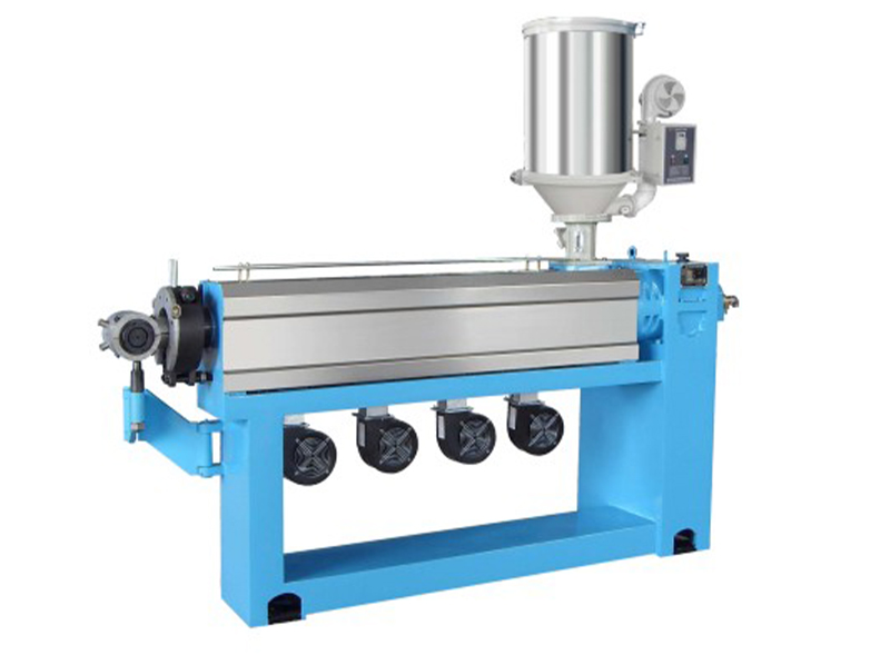
Transitioning from static steel to a humming production line requires a highly methodical approach. Rushing the physical assembly is a guaranteed recipe for mechanical failure.
The physical anchoring dictates the long-term vibration resistance of the line. Begin by maneuvering the main extruder body onto the designated chalk centerline. Technicians must use precision laser alignment tools to ensure the extruder barrel sits perfectly horizontal.
Once leveled, the main body is permanently anchored using heavy-duty chemical expansion bolts. Subsequently, the payoff, cooling trough, and capstan must align along that exact same optical axis. The entire wire path must be arrow-straight. This prevents the bare conductor from scraping against the internal tooling.
With the heavy iron bolted down, delicate electrical integration commences. This phase involves routing heavy-gauge power cables from the main distribution panels directly into the primary control cabinet. Careful attention must be paid when wiring the delicate thermocouple sensors across the heating zones.
Technicians must use heavily shielded cables for all sensitive connections to prevent electromagnetic interference. This includes in-line laser diameter gauges, high-frequency spark testers, and dancer position sensors. Proper earth grounding of the human-machine interface panels is critical for operator safety and data integrity.
Validating your capital expenditure requires a deep technical understanding of machine architectures. The physical setup, tooling geometry, and thermal parameters vary wildly depending on the final cable application. Choosing the wrong configuration leads to massive material waste.
Equipment Type | Core Application | Key Engineering Parameters | Setup Focus |
|---|---|---|---|
Sheathing Line | Thick outer protective jackets for multi-core power cables. | 90mm-120mm screw diameter, L/D ratio 25:1, Output up to 250 kg/h. | Requires extended multi-stage cooling troughs to handle massive polymer volume without shrinkage. |
High-Efficiency Line | High-speed building wires and primary insulation. | 50mm-70mm barrier screw, Line speeds exceeding 500 m/min, advanced PLC touch control. | Strict synchronization between capstan speed and screw RPM using closed-loop laser feedback. |
Heating Cable Line | Underfloor heating cables and delicate resistance wires. | Ultra-sensitive tension control, precise proportional-integral-derivative thermal management. | Payoff tension calibration is paramount to prevent stretching the fragile inner alloy wire. |
Fluoroplastics Line | Aerospace, military, and extreme high-temperature environments. | Hastelloy anti-corrosion screw, processing temperatures exceeding 400°C. | Mandatory heavy-duty overhead ventilation for corrosive off-gasses; specialized alloy tooling. |
When a factory needs to apply a thick protective outer jacket over a bundled power cable, standard primary extruders fall short. This heavy-duty application requires setting up a dedicated sjn(gx)-90 sheathing line. This specialized machinery features a larger L/D ratio and is engineered to push massive volumes of polymer at lower pressures.
Setting up a sheathing line requires accommodating significantly larger crossheads designed to swallow thick inner cables. Because the volume of extruded plastic is exponentially higher, the cooling infrastructure must be drastically enhanced. Operators must configure extended cooling troughs with high-capacity turbulent water circulation. This ensures the thick outer jacket cools evenly, preventing severe surface warping.
For standard building wires, output speed is everything. Deploying a high-efficiency cable extrusion line allows factories to hit speeds well over 500 meters per minute. The setup focus here is entirely on digital synchronization. The PLC must be perfectly tuned so the barrier screw output dynamically matches the capstan haul-off speed. If this digital handshake fails, the cable diameter will fluctuate wildly.
Manufacturing cables that generate heat involves handling incredibly delicate resistance wires. A dedicated heating cable extruding line demands ultra-precise tension control at the payoff. If the tension is even slightly too high, the fragile inner alloy wire will stretch. This permanently alters its electrical resistance properties and ruins the product.
Furthermore, the extruder screw design must be custom-tailored to process cross-linked compounds. The setup requires configuring highly sensitive temperature controllers. A temperature deviation of just one or two degrees can degrade the specialized compounds used for thermal applications.
Cables destined for aerospace or extreme industrial environments are insulated with advanced materials like FEP, PFA, or PTFE. Setting up a high-temperature fluoroplastics extruding line introduces extreme metallurgical challenges. These plastics release highly corrosive off-gasses when melted at temperatures exceeding 400°C. Standard steel components will rapidly disintegrate. During installation, engineers must verify that the barrel, screw, and crosshead are forged from specialized anti-corrosion alloys like Hastelloy.
Once the line is mechanically anchored and electrically live, the commissioning phase begins. This bridges the gap between static machinery and profitable production. Precision calibration takes over here.
Before the operator ever touches the main drive start button, the extruder barrel and massive steel crosshead must achieve precise operating temperatures. Establishing an ascending temperature profile across the barrel zones ensures the raw polymer melts gradually.
Crucially, technicians must enforce a strict heat soak period. Even after the screen indicates the target temperature is reached, the dense internal metal components require an additional 45 to 60 minutes to fully equalize. Attempting to rotate the screw before a complete heat soak results in catastrophic mechanical failure. Unmelted plastic chunks will literally shear the heavy steel screw flights.
Achieving perfect concentricity is vital for passing strict international electrical safety standards. The copper conductor must sit exactly dead-center within the plastic jacket. During the initial startup, technicians run the line at a crawl and slice a cross-sectional sample of the hot cable.
Placing this sample under an optical profile projector, they measure the wall thickness on all four quadrants. By adjusting the micro-threading centering bolts on the crosshead die, the operator physically shifts the flow of the melt. They repeat this until the insulation is perfectly uniform 360 degrees around the core.
Even with meticulous preparation, initial production runs inevitably reveal setup inconsistencies. Identifying the root cause promptly minimizes expensive scrap and prevents equipment damage.
If the outer diameter fluctuates rhythmically, creating a lumpy appearance, the issue is rarely the extruder itself. It is typically related to mechanical speed or wire tension. First, observe the dancer arm at the payoff. If it is bouncing erratically, the pneumatic tension settings require immediate recalibration. If the tension is dead-stable, inspect the primary feeding zone for bridging. Bridging occurs when pellets clump together and starve the screw.
A rough, matte, or shark-skin texture on the cable jacket indicates a severe material flow issue known as melt fracture. Melt fracture typically occurs when operators process the polymer at too low a temperature. Forcing cold material through a restrictive die creates immense shear stress. The immediate solution is to adjust the temperature profiles slightly upward to lower the viscosity. Additionally, ensure the raw plastic pellets are thoroughly dried. Trapped moisture boils during extrusion, blowing microscopic craters in the cable surface.
In-line spark testers apply thousands of volts to the finished cable to detect invisible pinholes. Frequent spark test failures during a new setup point to contamination or severe thermal shock. Inspect the raw compound for degraded black specks. More importantly, ensure the bare copper wire passes through an induction pre-heater before entering the crosshead. Applying hot plastic to a cold wire causes the plastic to shrink violently away from the metal. This creates micro-voids that instantly fail under high voltage.
The initial setup is merely the first chapter of the equipment lifecycle. To guarantee relentless, long-term profitability, factory management must implement structured post-installation protocols.
High-speed production demands uncompromising maintenance schedules. Maintenance teams must establish firm routines for pulling and brass-brushing the extruder screw. This prevents degraded material from building up in the flights. Regularly inspect and swap out the breaker plate screens to filter rogue impurities. Furthermore, utilizing thermal imaging to monitor gearboxes allows teams to predict wear long before a mid-run failure occurs.
The most sophisticated machinery cannot compensate for an untrained operator. Comprehensive hands-on training regarding the supervisory control systems is paramount. Operators must know exactly how to save, optimize, and recall specific product recipes. Shaving just twenty minutes off a tooling changeover directly increases total factory output.
To achieve zero-defect manufacturing, facilities must lean into automated systems. Ensure closed-loop diameter controllers are active. Integrate optical lump and neck detectors alongside spark testers to automatically flag deformities. Relying on automated in-line quality control rather than manual batch testing slashes scrap rates.
Properly setting up wire and cable manufacturing equipment is a demanding synthesis of heavy mechanical engineering and precise digital automation. Investing the necessary time into a flawless initial setup pays off exponentially. Ready to upgrade your factory floor and eliminate costly downtime? Explore the full range of cutting-edge, application-specific extrusion solutions at Anhui SJ to ensure your next production line runs flawlessly from day one.
The required linear footprint varies based on the polymer application and target production speed. A standard layout typically demands 30 to 60 meters in a straight line. High-speed lines require significantly longer cooling troughs to ensure the plastic cures completely before spooling. Ample space must also be allocated around the payoff stands for forklift access. A perfectly straight, reinforced foundation is mandatory to prevent wire path misalignment.
High-efficiency models are engineered to maximize volumetric throughput while drastically minimizing electrical energy consumption. They feature advanced programmable logic controls, optimized barrier screw designs, and automated closed-loop diameter feedback systems. These modern lines utilize energy-efficient vector drives and heavily insulated ceramic heating zones, significantly reducing the factory electrical load compared to older machinery.
Optimal cooling requires a staged temperature gradient rather than a single cold bath. The first cooling zone immediately after the crosshead should typically be maintained around 60°C to 70°C to prevent thermal shock and surface crystallization. As the cable progresses down the trough, subsequent zones gradually drop the temperature down to 20°C. This graduated process ensures the polymer chains relax and cure without inducing internal stress fractures.
Preventing wire breakage relies entirely on flawless tension control at the payoff stand. Utilizing a motorized payoff paired with a highly responsive pneumatic dancer arm is critical. The dancer arm absorbs sudden mechanical jerks and continuously sends position data back to the main drive. By keeping the back-tension perfectly stable and ensuring the induction pre-heater is not overheating and softening the copper, operators can run at maximum speeds without snapping the core.
An off-center jacket is almost exclusively a tooling alignment or core tension issue. First, verify that the internal guider tip and the outer die are concentrically aligned within the crosshead. Use the micro-centering bolts to adjust the polymer melt flow. If the steel tooling is perfectly aligned, inspect the incoming core cable. If the heavy core lacks adequate back-tension from the payoff, it will sag as it passes through the crosshead, resulting in a wildly uneven jacket thickness.
The timeline depends on machinery complexity and facility utility readiness. Generally, physical mechanical anchoring and electrical wiring take one to two weeks. This is followed by a rigorous commissioning phase lasting three to five days. During this window, engineers perform heat soak tests, calibrate laser sensors, synchronize drive speeds, and run live material trials to ensure the finished cable strictly meets all dimensional standards.