

Views: 0 Author: Site Editor Publish Time: 2026-08-12 Origin: Site


Mis-sizing extrusion equipment triggers severe operational consequences for any manufacturing facility. You face chronic production bottlenecks when machines cannot keep up with downstream demand. Polymer degradation occurs rapidly from excessive shear in improperly specified barrels. Unjustified capital expenditure on oversized machinery drains engineering resources without delivering proportional output gains. The core engineering challenge remains clear on the factory floor. You must balance line speed, material rheology, and precise conductor dimensions. Operators must maintain strict concentricity and wall thickness tolerances at all times to meet industry standards. We will introduce a systematic framework for specifying a wire and cable extruder. This guide moves from baseline production targets to technical specifications. We cover application-specific configurations, screw geometries, and advanced risk mitigation strategies to ensure your line runs continuously without generating excessive scrap.
Extruder sizing must begin with defining the minimum and maximum conductor size range and the specific rheological properties of the primary polymers (e.g., PVC, XLPE, PE, LSZH).
Screw diameter and Length-to-Diameter (L/D) ratios dictate melt quality and throughput; mismatches lead to un-melted particles or thermal degradation.
A high efficiency wire and cable extruder relies heavily on synchronized downstream equipment—specifically, cooling trough length and tension control—to maintain structural integrity at high line speeds.
Evaluating control systems for real-time closed-loop feedback (diameter, capacitance, and concentricity) is as critical as the mechanical sizing of the barrel and screw.
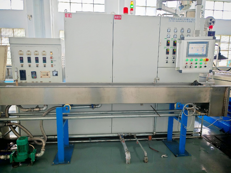
Calculating required throughput establishes the baseline for machine sizing. You must determine the target output in kilograms per hour (kg/hr) or pounds per hour (lbs/hr). This calculation relies on your target line speeds, measured in meters or feet per minute. The formula requires multiplying the cross-sectional area of the applied polymer by the line speed and the specific gravity of the material. This provides the exact volumetric output required from the extruder. Running a 2.5mm² wire with a 0.8mm wall thickness at 500 meters per minute demands a vastly different melt capacity than running a 50mm² power cable at 50 meters per minute.
A direct relationship exists between conductor cross-section, insulation thickness, and volumetric output. Heavy wall thicknesses on large conductors demand massive volumetric flow. Thin-wall insulation on fine wires requires low volume but exceptionally high line speeds. You must map the extruder capacity against the full 8-stage production line to prevent systemic bottlenecks.
Payoff system for bare conductor delivery under controlled tension.
Inline wire drawing or pre-heating stations to prepare the copper.
The main extrusion crosshead and tooling assembly.
Primary water cooling trough utilizing a warm water zone.
Secondary water cooling trough utilizing a chilled water zone.
Capstan pulling mechanism to dictate master line speed.
Inline testing equipment including spark testers and diameter gauges.
Accumulator and dual take-up spooler for continuous operation.
An oversized extruder creates systemic bottlenecks at the cooling trough. The machine pumps out plastic faster than the water can remove the heat. An undersized extruder stalls the capstan and limits overall line speed. You must establish strict baseline success metrics. These include minimizing scrap rates during startup, achieving consistent line speeds without motor stall, and maintaining dimensional stability across continuous operational shifts.
Different polymers dictate specific machine sizing parameters. Cross-linked polyethylene (XLPE) requires high shear rates for proper processing. Fluoropolymers are highly temperature sensitive. They require precise thermal control to prevent rapid degradation inside the barrel. Standard polyvinyl chloride (PVC) offers broader processing windows but still requires accurate temperature zoning to prevent burning.
The melt flow index (MFI) and viscosity of the polymer directly impact drive power and torque requirements. High viscosity polymers demand significant torque at lower screw speeds. Low viscosity materials require higher RPMs to maintain pressure in the crosshead. You must outline the necessity of matching the machine to the primary insulation material. Finalize your material specifications before locking in mechanical machine parameters.
Temperature profiles vary wildly between materials. PVC extrudes around 150°C to 180°C. XLPE requires a gradual ramp up to 130°C in the barrel but crosslinks at temperatures exceeding 200°C in the continuous vulcanization (CV) tube. Fluoropolymers require barrel temperatures exceeding 350°C, necessitating specialized Hastelloy barrels to prevent corrosive wear on the internal components.
Polymer Type | Specific Gravity | Typical Extrusion Temp | Machine Sizing Impact |
|---|---|---|---|
Standard PVC | 1.38 - 1.45 | 150°C - 180°C | Standard L/D ratios, moderate torque requirements. |
Polyethylene (PE) | 0.92 - 0.95 | 180°C - 210°C | Requires longer L/D ratios for thorough melting. |
XLPE | 0.92 - 0.93 | 110°C - 130°C (Barrel) | High shear requirements, barrier screws recommended. |
Fluoropolymers (FEP/PTFE) | 2.10 - 2.20 | 350°C+ | Corrosion-resistant barrels, high-temperature heaters. |
Standard L/D ratios range from 24:1 to 30:1. Each ratio serves specific use cases in wire coating. A 24:1 ratio suits standard PVC processing where shorter residence times prevent material degradation. A 30:1 ratio provides the longer residence time necessary for melting polyethylene (PE) or XLPE thoroughly. Screw diameter determines the maximum theoretical output of the machine. It also dictates the residence time of the polymer inside the heated barrel.
Mismatched L/D ratios cause severe production defects. Too short of a barrel leaves un-melted particles in the insulation, causing spark test failures. Too long of a barrel risks thermal degradation of sensitive compounds. You must evaluate the trade-offs of using universal screws versus material-specific screw profiles. Universal screws offer flexibility for facilities running multiple compounds. Material-specific designs, like barrier screws or those with Maddock mixing sections, ensure superior melt homogeneity.
Screw Diameter | Typical Application | Estimated Output Range (PVC) |
|---|---|---|
30mm - 45mm | Fine wire, automotive wire, fiber optic buffering | 15 kg/hr - 60 kg/hr |
60mm - 70mm | Building wire, standard data cables | 80 kg/hr - 150 kg/hr |
90mm - 120mm | Low voltage power cables, heavy jacketing | 250 kg/hr - 500 kg/hr |
150mm+ | High voltage power cables, subsea cables | 600 kg/hr+ |
Engineering calculations dictate the required extruder motor size in kilowatts (kW) or horsepower (HP). You base these calculations on polymer viscosity and target screw RPM. Processing stiff or highly filled materials requires high torque at low screw speeds. Low smoke zero halogen (LSZH) compounds are notoriously stiff. They demand robust gearbox configurations to prevent motor stall during continuous operation.
Gearbox reduction ratios play a massive role in torque delivery. A 15:1 reduction ratio provides high speed for thin walls. A 25:1 ratio provides massive torque for heavy sheathing. The thrust bearing absorbs the backpressure from the crosshead. A 10,000 psi backpressure requires a heavy-duty tandem thrust bearing to prevent catastrophic gearbox failure.
Modern extrusion lines utilize different motor technologies. You must compare AC vector drives against permanent magnet synchronous motors (PMSM). AC vector drives provide reliable power for standard PVC lines. PMSM technology delivers maximum torque at zero speed, making it ideal for heavy sheathing applications.
Motor Technology | Torque Delivery | Energy Efficiency | Best Application |
|---|---|---|---|
AC Vector Drive | Consistent across mid-to-high RPM | Standard baseline efficiency | General purpose PVC/PE extrusion |
PMSM (Permanent Magnet) | High torque at very low RPM | Exceptional energy savings | Stiff compounds (LSZH, XLPE) |
Primary insulation requires specific machine capabilities. You deal with thin walls, high line speeds, and precise concentricity requirements. A Wire and Cable Extruder for Insulation and Jacketing must maintain absolute pressure stability. Pressure fluctuations cause immediate wall thickness variations. You must evaluate the integration of inline wire drawing systems. These systems reduce bare wire diameter through a die just before extrusion.
Inline drawing requires seamless speed synchronization with the extrusion crosshead. The extruder must also integrate with conductor pre-heaters. Pre-heating the bare copper ensures proper polymer adhesion. It drives off residual moisture that causes voids in the insulation. Crosshead design plays a major role here. Fixed center crossheads reduce operator adjustment errors during high-speed runs. Adjustable center crossheads offer necessary flexibility for varying insulation profiles.
Tooling types dictate the final product quality. Pressure tooling forces the polymer into the conductor interstices, making it ideal for stranded wire. Sleeving tooling, also known as tube-on tooling, draws the polymer down onto the conductor. This method is ideal for high-speed data cables where easy stripping is required during installation.
Sheathing and jacketing requirements contrast sharply with primary insulation. You handle larger overall cable diameters. You apply heavier wall thicknesses. You operate at significantly lower line speeds. Specifying a Wire and Cable Extruder for Cable Sheathing requires higher output capacities. This necessitates larger screw diameters to move massive volumes of polymer over multi-core bundles.
Outer jacketing often covers multi-core cables. You must address the integration of vacuum systems in the crosshead. A vacuum pulls the molten polymer tight over the inner cores. This ensures a tight, uniform sheath. It eliminates trapped air pockets between the cores and the outer jacket. The tooling design must accommodate the irregular shapes of twisted inner conductors without tearing the hot polymer.
Operators frequently use talc or mica powder applicators before the crosshead to prevent the hot jacket from fusing to the inner cores. You must also specify caterpillar haul-offs for large cables. Caterpillar tracks distribute the pulling force over a larger surface area to prevent crushing the core, unlike standard wheel capstans.
Selecting between co-extrusion and tandem extrusion requires a strict decision matrix. Co-extrusion applies multiple layers in a single crosshead. Common applications include skin/foam/skin configurations for data cables. The inner skin ensures adhesion to the copper. The foamed middle layer utilizes nitrogen gas injection to reduce the dielectric constant. The outer skin provides mechanical protection. This method saves floor space and ensures excellent layer adhesion. However, tooling design is highly complex, and purging the crosshead takes longer.
Tandem extrusion applies layers sequentially across multiple crossheads. You might apply primary insulation, cool the wire, and then apply a nylon jacket. You must discuss the footprint and synchronization challenges. Sizing secondary extruders for striping or thin skin layers requires careful capacity matching. Both extruders must track the master line speed perfectly to prevent layer variations.
Defining a High Efficiency Wire and Cable Extruder requires looking at specific energy consumption. You measure this in kilowatt-hours per kilogram (kWh/kg) of processed material. Lower numbers indicate better mechanical and electrical design. You must evaluate the efficiency of different barrel heating and cooling systems. Cast-in aluminum heaters provide uniform heat distribution across the barrel zones.
Ceramic band heaters retain heat longer than standard aluminum heaters, reducing the duty cycle of the contactors. Utilizing solid-state relays (SSRs) provides precise temperature control compared to mechanical contactors. Cooling zones are equally important. Air cooling zones handle standard polymers effectively. Water cooling zones provide aggressive temperature control necessary for high-shear materials.
You must discuss the return on investment for insulated barrels. Insulation prevents ambient heat loss. Regenerative drive systems capture braking energy from the payoff and capstan. They feed this power back into the main grid, lowering overall consumption.
Mechanical sizing must pair with advanced control systems. Programmable Logic Controllers (PLCs) and Human-Machine Interfaces (HMI) form the brain of the line. You must detail the integration of inline measurement tools. Laser diameter gauges monitor outer dimensions continuously. Lump and neck detectors identify surface flaws instantly. Capacitance monitors check the dielectric integrity of data cables.
Advanced diameter gauges utilize Fast Fourier Transform (FFT) analysis. FFT detects periodic variations in the cable diameter. These variations usually point to a mechanical issue like a bent screw, a damaged capstan belt, or a vibrating payoff spool. Continuous inline inspection is mandatory at high line speeds. Speeds exceeding 1,000 feet per minute leave no room for manual measurement.
The system ensures the product remains compliant before it is coiled onto a spool. Closed-loop feedback connects the measurement gauges directly to the drives. The system automatically adjusts screw speed and capstan speed. This maintains strict tolerances without human intervention.
Undersizing the cooling trough presents a massive implementation risk. Insufficient cooling leads to severe insulation deformation. The cable hits the capstan while the polymer remains soft. This causes ovality, flattening, or internal voids. You must provide the framework for calculating cooling capacity accurately.
Calculations require analyzing the total polymer mass applied per minute. You must factor in the specific heat of the chosen material. You must account for the maximum projected line speed. Water temperature zones must step down gradually. Plunging hot XLPE directly into chilled water causes shock cooling. This introduces severe internal stress and shrinks the insulation away from the conductor.
Space-constrained factories utilize multi-pass cooling troughs. A multi-pass system routes the wire back and forth over sheaves inside the trough. This triples the cooling time within the exact same floor footprint, ensuring the polymer solidifies completely before hitting the capstan.
Poor synchronization ruins product quality instantly. You face the risk of conductor stretching. Fine wires snap under excessive tension. Copper dust generation occurs if inline drawing slips. The payoff, inline wire drawing machine, extruder, and take-up spooler must track together perfectly.
Mitigation requires specific hardware integration. You must specify multi-zone tension control systems. Dancer control uses physical weight or pneumatic pressure to maintain tension and absorb shock. Load cell control provides precise electronic tension measurement without moving parts, making it ideal for delicate fiber optics or fine copper.
Install precision dancers to absorb minor speed fluctuations. Utilize properly sized accumulators. Accumulators store finished wire temporarily. This allows continuous coiling and seamless spool changeovers without stopping the extruder.
Excessive scrap during machine startup destroys profit margins. Color changes and material changeovers waste expensive polymer. You must analyze these hidden costs. Incorporate standard startup procedures immediately upon installation. Conduct rigorous power supply and electrical system checks. This prevents cold starts that can snap the extruder screw.
Running a high-viscosity purge compound through the barrel removes degraded polymer and carbon buildup before switching to a lighter color or different material. Size the extruder with optimized flow channels in the crosshead. Eliminate dead zones where polymer stagnates and degrades.
Utilize automated startup sequencing in the PLC. This ramps up temperatures and speeds systematically. It minimizes transition times and reduces scrap generation dramatically.
Conduct a comprehensive audit of current production bottlenecks to identify true capacity limits on your existing lines.
Define strict minimum and maximum AWG/mm² ranges for your facility before requesting equipment quotes.
Request OEM pilot testing for specialized or highly filled polymers to verify screw design and melt homogeneity.
Calculate required cooling trough lengths based on your fastest projected line speed and thickest insulation wall.
A: Standard L/D ratios range from 24:1 to 30:1. A 24:1 ratio handles standard PVC processing efficiently. A 30:1 ratio provides the longer residence time necessary for melting polyethylene (PE) or cross-linked polyethylene (XLPE) without causing thermal degradation.
A: Calculate required output by determining the cross-sectional area of the polymer jacket. Multiply this area by the target line speed and the specific gravity of the sheathing material. This yields the exact volumetric output required from the extruder to maintain that speed.
A: Primary insulation extruders focus on high speeds, thin walls, and precise concentricity, utilizing smaller screw diameters. Outer jacketing extruders handle larger cable diameters, heavier wall thicknesses, and lower speeds. They require larger screw diameters to deliver higher volumetric output.
A: Higher line speeds require the screw to melt and pump polymer faster, demanding specific L/D ratios and motor torque. Faster speeds also mean the hot cable spends less time in the cooling trough, necessitating significantly longer troughs to prevent deformation at the capstan.
A: Wall thickness variations stem from pressure fluctuations inside the crosshead. These fluctuations result from inconsistent screw RPM, poor melt homogeneity, surging in the barrel, or poor synchronization between the extruder output and the capstan pulling speed.
A: XLPE requires high shear for proper cross-linking, often utilizing barrier screws. LSZH is highly viscous and stiff, requiring screws with optimized compression ratios and robust gearboxes to handle the high torque demands without stalling the motor.
A: Inline wire drawing reduces bare wire diameter right before coating. If the drawing speed and extruder capstan speed lack perfect synchronization, the bare conductor will stretch, snap, or cause severe concentricity failures as it passes through the extrusion crosshead.